Ignition Coil Wiring Diagram / MicroSquirt V3 Coils : On 06 jetta 2.5 cylinder 1 ignition coil wiring diagram.. That's right, unhook the ignition grounding lead from the coil itself and use the spark tester. Wiring diagram for ignition coil more information find this pin and more on 63 f100 wiring by ben platt. Wire diagram for most b s engines. The wired differences matt dixon southern illinois university carbondale,. Briggs engine 125k02 0137 ignition system.
Bank 1 is always on cylinder 1 side. It shows the components of the circuit as simplified shapes, and the capacity and signal friends between the devices. 4.3 vortec ignition coil wiring diagram. However, this diagram is a simplified variant of this arrangement. Stens ignition coil briggs stratton 298968 460 006.
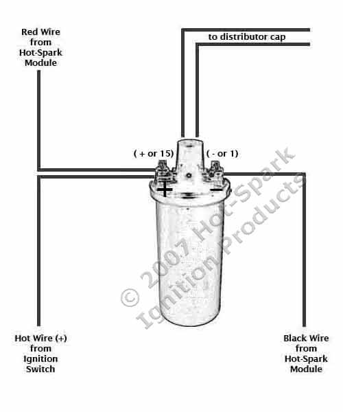
Compatible Ignition Coils, Ballast Resistors, Hot-Spark ... from www.hot-spark.com One trick that i use is to print exactly the same wiring picture off twice. 12 volt ignition coil wiring diagram accuspark diagrams 1929 a 6v to 12v help ford 8n tractor ferguson 9n 1 wire john deere model switch sel basic system 5 4 8 primary full johnson outboard 6 9 600 image details 1955 thunderbird dyna electronic key 48 systems short course you understand how motorcycle your boat 1953 v starter 1988. Stens ignition coil briggs stratton 298968 460 006. Rewiring a dynamark ignition switch lawnsite is the largest and most active online forum serving green industry professionals. The coils which are the basis for ignition coils and alternators have very specific electronic. Because the output spark is very much higher voltage (20,000v) than the car battery (12v), it doesn't care if the battery polarity is helping or hindering by a meager 12 to 14 volts in battery potential. The simple fix for this is to reverse the two primary wire connections on the ignition coil. This tutorial will help you test the ignition coil, ignition module, and the crankshaft position sensor (pickup coil):
Bank 2 is the opposite side of bank 1.
Inspect the ignition system related switches for correct continuity according to the service manual or wiring diagram. The wired differences matt dixon southern illinois university carbondale,. Print the cabling diagram off plus use highlighters to be able to trace the circuit. The ignition coil is nothing more that an electrical transformer. The ecu sends a signal and each module is responsible to power one coil at the right time. 1 trick that we use is to print the same wiring picture off twice. Ignition system ignition coil motorcycle wiring scrambler motorcycle motorcycles honda civic engine remote car starter trailer wiring diagram boat wiring. This tutorial will help you test the ignition coil, ignition module, and the crankshaft position sensor: The aftermarket cdi module must be placed between ecu signal and coil, jumping the stock power modules. Ford ignition coil wiring diagram wiring diagram is a simplified enjoyable pictorial representation of an electrical circuitit shows the components of the circuit as simplified shapes and the gift and signal friends amid the devices. Ignition solutions for older small engines and garden pulling tractors. The typical automotive ignition system prior to 1974 consisted of a coil and ballast resistor, with breaker points to interrupt the current flow when a spark was needed. The factory wiring diagram will need to be traced for further testing.
The coil primary winding contains 100 to 150 turns of heavy copper wire. This tutorial will help you test the ignition coil, ignition module, and the crankshaft position sensor (pickup coil): Print the cabling diagram off plus use highlighters to be able to trace the circuit. The wired differences matt dixon southern illinois university carbondale,. Briggs engine 125k02 0137 ignition system.
Mallory Ignition Wiring Diagram | Free Wiring Diagram from ricardolevinsmorales.com On 06 jetta 2.5 cylinder 1 ignition coil wiring diagram. If one is suspect, perform the outlined checks exactly as mentioned. Ignition coil ballast resistor wiring diagram welcome to my internet site this blog post will certainly discuss concerning ignition coil ballast resistor wiring diagram. This makes the procedure for assembling circuit easier. It shows the parts of the circuit as streamlined forms, and the power as well as signal links in between the tools. Basic ignition system wiring diagram. When you use your finger or even follow the circuit together with your eyes, it is easy to mistrace the circuit. One trick that i use is to print exactly the same wiring picture off twice.
Bank 2 is the opposite side of bank 1.
Wiring diagram for ignition coil. 12 volt ignition coil wiring diagram accuspark diagrams 1929 a 6v to 12v help ford 8n tractor ferguson 9n 1 wire john deere model switch sel basic system 5 4 8 primary full johnson outboard 6 9 600 image details 1955 thunderbird dyna electronic key 48 systems short course you understand how motorcycle your boat 1953 v starter 1988. This wire must be insulated so that the voltage does not jump from loop to loop, shorting it out. In the years when engines were a lot easier to work with a ballast resistor was used in order to prolong the life of the coil. Ignition coil ballast resistor wiring diagram. When you use your finger or even follow the circuit together with your eyes, it is easy to mistrace the circuit. The purpose of the ignition system is to create a spark that will ignite the fuel air mixture in the cylinder of an engine. The coils which are the basis for ignition coils and alternators have very specific electronic. Stens ignition coil briggs stratton 298968 460 006. The crank position sensor and exciter coil often must be replaced with the stator as an assembly. On 06 jetta 2.5 cylinder 1 ignition coil wiring diagram. This applies to all old cub cadet ford jacobsen john deere wheel horse case and. As in the diagram below, most ignition coils share the same fuse and/or relay that feeds the power supply.
The job of the ballast resistor was to inhibit current to a level that would not overheat the coil. Basic key wiring diagram 48 volt battery begeboy source. Ignition system ignition coil motorcycle wiring scrambler motorcycle motorcycles honda civic engine remote car starter trailer wiring diagram boat wiring. Basic ignition system wiring diagram. March 12, 2019 by larry a.
Ignition Coil Distributor Wiring Diagram - Wiring Forums from i0.wp.com The purpose of the ignition system is to create a spark that will ignite the fuel air mixture in the cylinder of an engine. 4.3 vortec ignition coil wiring diagram. The simple fix for this is to reverse the two primary wire connections on the ignition coil. Because the output spark is very much higher voltage (20,000v) than the car battery (12v), it doesn't care if the battery polarity is helping or hindering by a meager 12 to 14 volts in battery potential. A wiring diagram is a streamlined standard photographic representation of an electric circuit. This makes the procedure for assembling circuit easier. Wellborn variety of mercruiser ignition wiring diagram. One trick that i use is to print exactly the same wiring picture off twice.
Bank 1 is always on cylinder 1 side.
The ecu sends a signal and each module is responsible to power one coil at the right time. March 12, 2019 by larry a. Wiring diagram for ignition coil. 1 trick that we use is to print the same wiring picture off twice. Cylinder to cylinder variations are valuable. It shows the elements of the circuit as streamlined shapes, as well as the power and also signal links in between the tools. Wellborn variety of mercruiser ignition wiring diagram. A wiring diagram is a streamlined standard photographic representation of an electric circuit. In the years when engines were a lot easier to work with a ballast resistor was used in order to prolong the life of the coil. This tutorial will help you test the ignition coil, ignition module, and the crankshaft position sensor (pickup coil): That's right, unhook the ignition grounding lead from the coil itself and use the spark tester. The coil primary winding contains 100 to 150 turns of heavy copper wire. Rewiring a dynamark ignition switch lawnsite is the largest and most active online forum serving green industry professionals.